OpenPlant Modeler Help

Create a Custom Component

Use the workflow below for creating a custom component from geometrical graphical elements that exist in either the active drawing if creating a component for a one-time use (User Custom Component), or if creating a component in a cell library for re-use.
  1. Select the set of graphical elements in the drawing and click the Create New Custom Component icon from the Custom Components gallery.
    Note: The options in the dialog are disabled if no graphical elements are selected in the drawing.
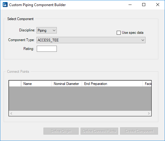
  2. Select a discipline from the list (Piping or Support).
  3. Select a Component Type from the list to activate the remaining fields in the dialog as shown below.
    Note: OpenPlant Modeler provides a basic set of component classes which can be used when creating a custom component (displayed in the Component Type list). However additional classes can be added to the list by adding the custom attributes to the class so they will be available when creating custom components. This is done by modifying the component class in the OpenPlant 3D Supplemental Modeling schema located in the Workspace\Projects\%Project%\Dataset\Schemas directory.
  4. Use the descriptions in the table below to assist in defining the fields in the Connect Points grid.
    Note: If the Use Spec Data option was enabled, the grid is automatically populated with the information from the active spec for the selected component type. If more than one record exists in the spec, you will be prompted to make a selection from the Spec Record Selection dialog.
    Note: The Use Spec Data, Connect Points and Define Connect Points options are not applicable when creating a Custom Support.
    Use Spec Data If this option is selected, the Connect Points properties are populated using the information from the active specification for the selected Component Type.

    If more than one record for the Component Type exists in the spec, then the Spec Record Selection dialog displays prompting you to select a specific record to use for the component.

    For example: If a Ball Valve is selected as a Component Type with this option enabled, then the Connect Point fields will be populated using the information from the specification.

    The current Nominal Diameter value from the Standard Preferences dialog is used for the component.

    Note: This option is not applicable when creating a Custom Support.
    Discipline Select from either Piping or Support. This determines what kind of component is created.
    Component Type Lists the available component types in the schema to choose from.
    Rating Input a rating for the component. This field is disabled when the Use Spec Data option is selected as the Rating value for the selected component is taken from the spec.
    Connect Points The Connect Point information grid is enabled displaying editable entries of Connect Point Information. The number of entries (rows) reflects the number of ports as defined in the schema for the selected Component type. (For Example, a Four Way Valve will have four port entries etc.)
    Note: Note that the values in the Connect Points fields are only editable when the Use Spec Data option is not enabled. Otherwise the fields are populated using defined values from the active specification.
    • Name: Reflects the name(s) of the ports defined for the selected Component Type.
    • Nominal Diameter: Select a value from the list if not using the current spec values.
    • End Preparation: The list will contain all of the available values for the selected component type.
    • Facing: List will contain the available facing option for the selected component type.
    Note: This option is not applicable when creating a Custom Support.
    Define Origin Click to pick a point on the component to use as an origin point.
    Define Connect Points You will be prompted to pick a point and define a direction for each listed port.
    Note: This option is not applicable when creating a Custom Support.
    Create Component Creates the component and displays the Modify Component dialog, allowing you to define additional property values for the component as necessary.
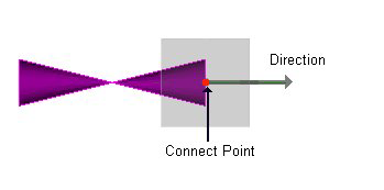
  5. Once the grid values have been defined, click the Define Origin button and pick a point on the component to use as the origin point.
    Note: A confirmation message displays in the status bar.
  6. Next, click the Define Connect Points button and define the location and direction of the connection point for each listed port in the grid as shown below.
  7. Follow the prompts in the status bar for the location and directional input.
    Note: When all of the ports have been defined, a confirmation message displays in the Status bar and the Create Component button will enable.
  8. Click the Create Component button. The Modify Component dialog displays allowing you to define property values for the component as needed. If creating a valve, you are able to define a tag number for the valve.
  9. Once you have defined the properties for the component, close the dialog to complete the process.
    Note: Edit Manipulators are not available for custom piping components.